Seismology Instruction with the AS 1
6. Carefully swing the boom up until it is possible to position the damping fl uid container
under the damping vane. Do not fi ll the container before it is positioned correctly.
CAUTION: Do not release the boom arm abruptly and allow the magnet to hit the coil. The
equipment is sensitive; handle and adjust the parts carefully and gently.
7. Add fl uid to the damping fl uid container. The fl uid level should be 1 cm (3/8 inch) below
the top of the container. For proper damping, the fl uid should be:
1/2 STP oil treatment and 1/2 10w40 synthetic motor oil for the thick spring units
(spring diameter of 8 mm)
1/3 STP oil treatment and 2/3 10w40 synthetic motor oil for the thin spring units
(spring diameter of 4 mm)
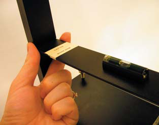
8. The boom arm must be level to accurately
(This position may vary)
record vertical motion. Begin by positioning the
bubble level on the boom, as shown in Figure 6.
Add or remove washers from the upright bolt and
if needed, add one or two washer(s) along the
boom until the boom is level. Move the washers
and the bubble level along the boom arm to fi ne
tune the leveling. The washer and bubble level
remain on the boom arm to keep it level.
Figure 6
9. Rotate the bubble level 90 degrees on the boom. Adjust
the base leveling screws until the bubble is again centered.
Rotate the bubble level 90 degrees back to its starting
position.
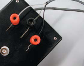
10. Check that the magnet is still centered above the coil.
Center the magnet over the coil by sliding the knife edge
at the support post (Figure 7). The boom arm should move
freely up and down and the magnet should not touch the coil.
Figure 7
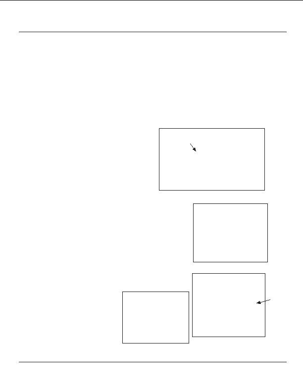
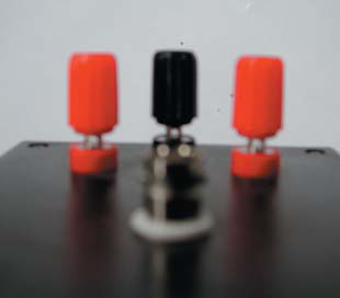
11. Attach the paired shielded coaxial cable to the interface
box. To attach a wire to a post the wire must pass through the
hole on the post (Figure 8) then tighten the plastic knob.
The center conductor of the
signal cable (uninsulated wire)
should be connected to the
ground terminal (black post) on
the interface box. The remaining
two insulated wires should be
connected to the two red posts
Figure 8
(Figure 9). Tighten until snug.
Figure 9
AmaSeis Version 1.0 Level 2005.05.19
2.3
footer
Our web partners:
Inexpensive
Web Hosting
Java Web Hosting
personal webspace
webspace php
linux webhost
html web templates
DreamweaverQuality Web Templates
PSD Web Templates
cheap webhost
j2ee web Hosting
buy webspace
ftp webspace
adult webspace
frontpage WebHosting
webspace hosting
cheap webhost
Visionwebhosting.net Business web hosting division of Vision Web Hosting Inc.. All rights reserved
earthlink web hosting